Hardware setup
Skeleton setup
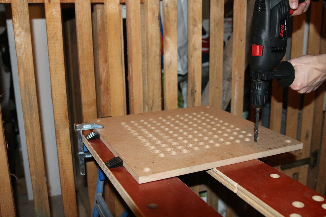
According to the stencil layout, for each LED a hole needs to be prepared. The total number of 114 holes makes this pretty tedious.
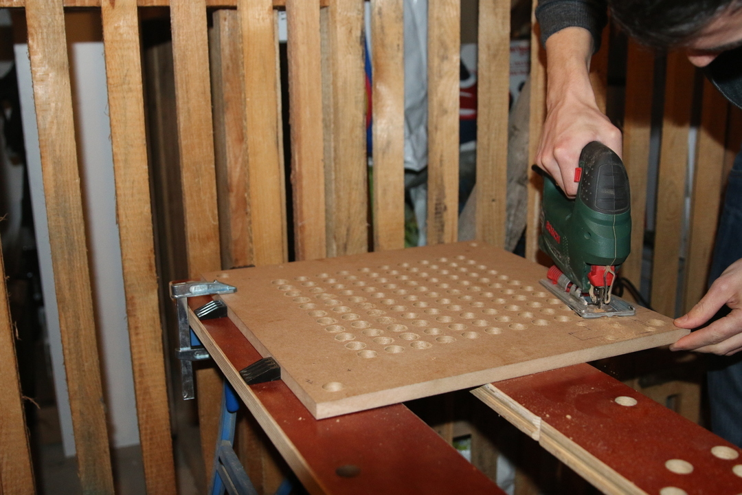
To place the Raspberry Pi within the skeleton, some sawing is required…
LED setup
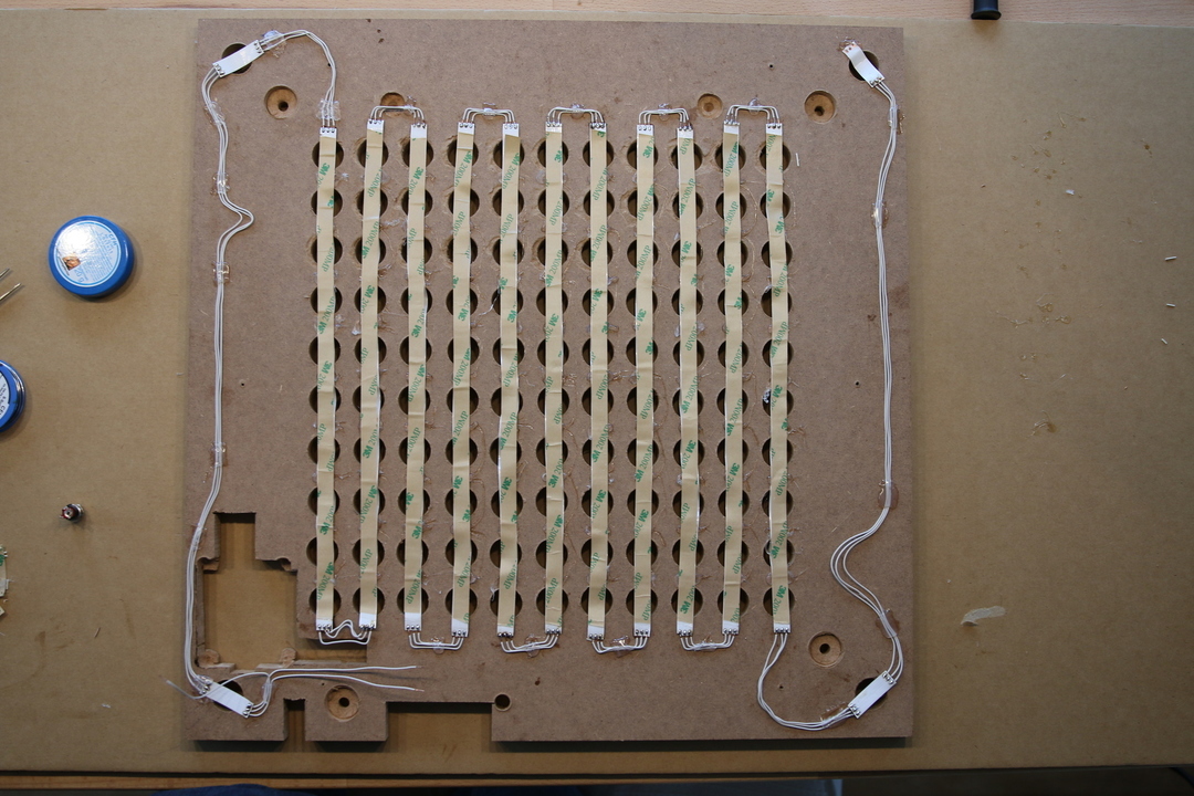
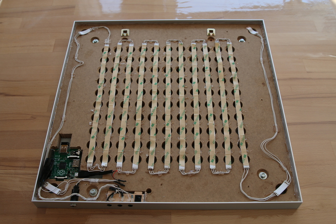
After soldering the LED strip, the clock looks like this. The soldering needs to be done according to the wiring layout. E.g. based on 11*10 letters:
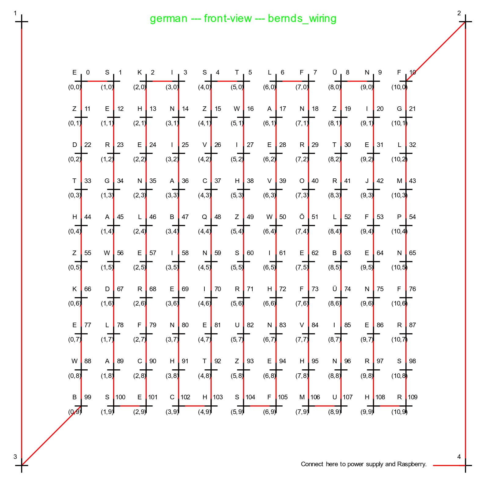
Further wiring layouts are available. Assure to connect the LED strip in the right direction. Little arrows indicate that along the strip.
Raspberry Pi setup
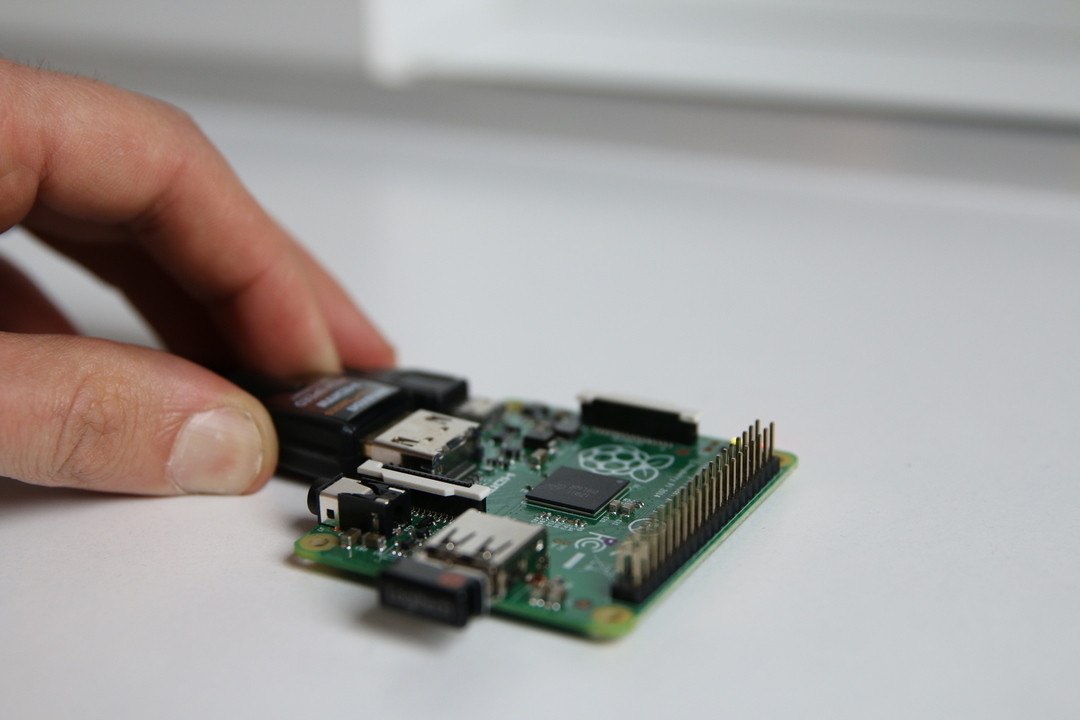
Before you mount your raspberry inside the clock, install the latest Raspbian, connect it to your local wifi and ensure that you can ssh to it.
Button setup
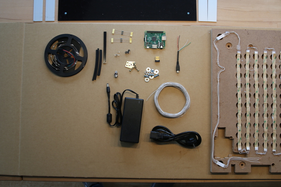
At this stage, the displayed components are required for the further setup.
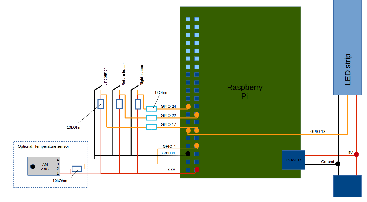
Conceptual wiring layout to connect RPi, buttons, etc. See also Power connectors, USB-Pinouts
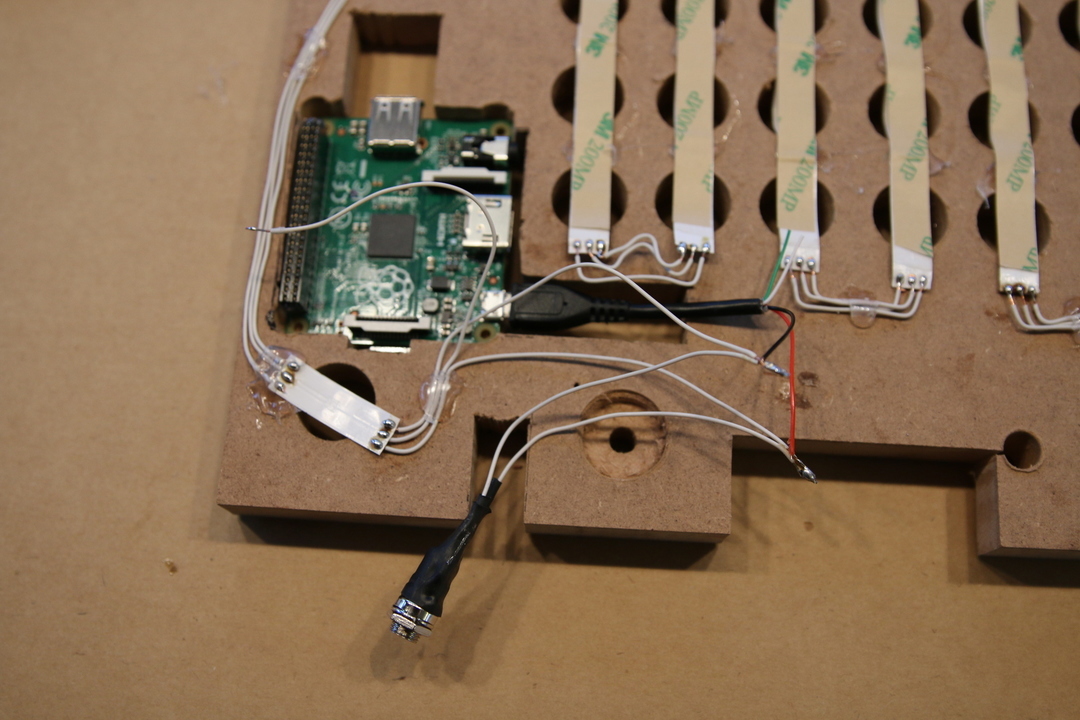
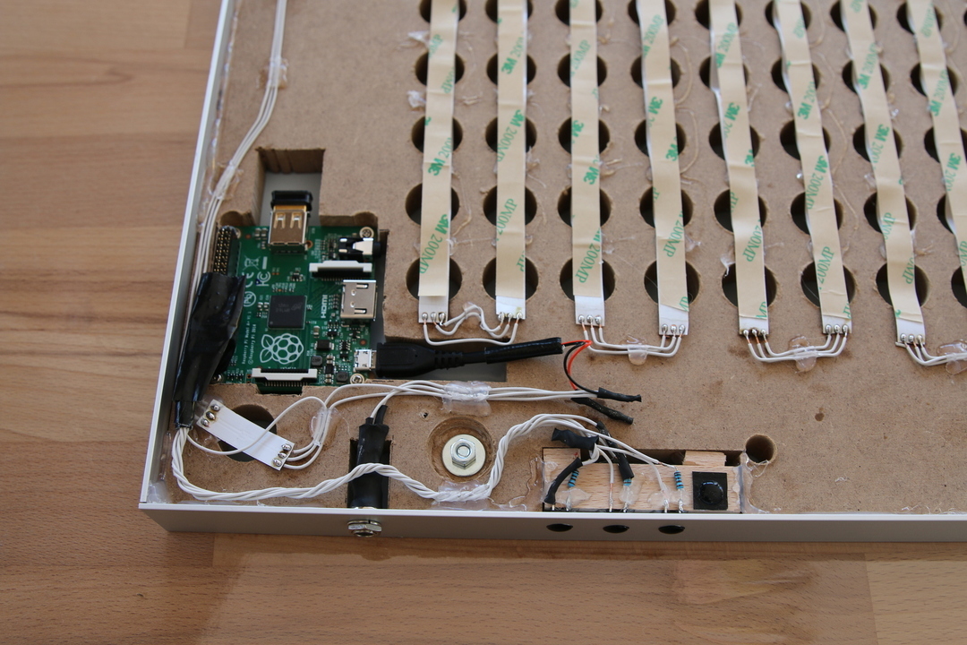
The connection of buttons, LED strip and power brings the wordclock close to its final hardware configuration.
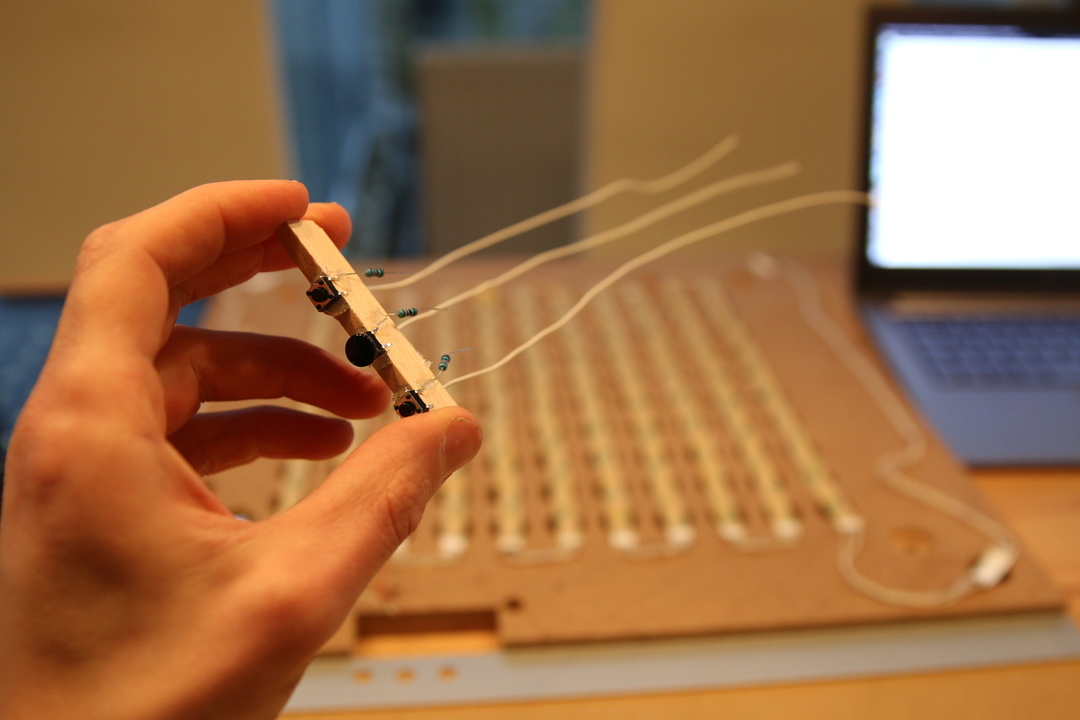
Buttons with attached resistors. The center button has already its final tip.
Stancil setup
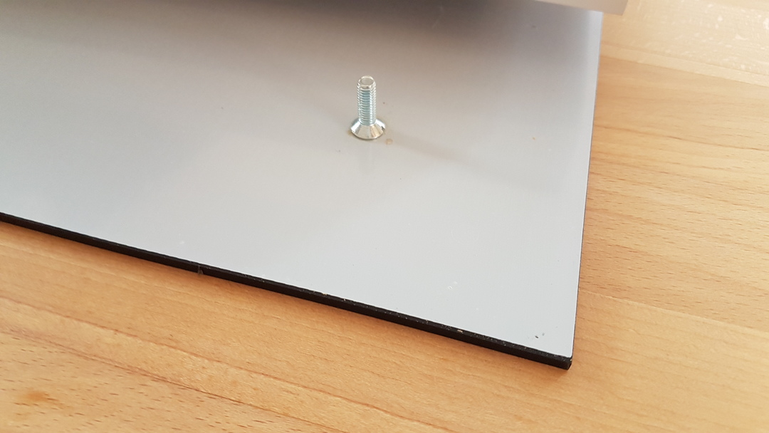
Fixation of 4 screws within the 4 corners of the stancil using two-component adhesive.
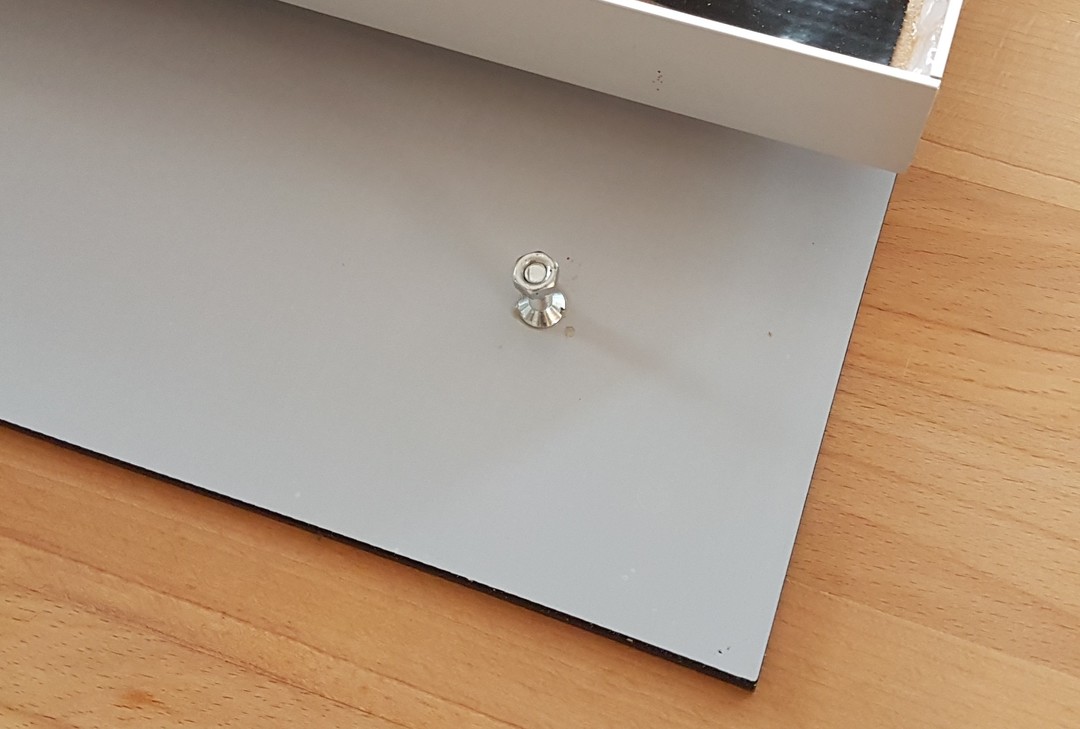
Allows to fix the stancil with screw-nuts to the sceleton.
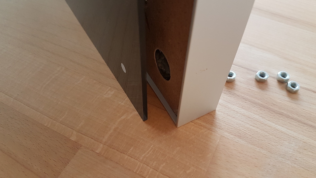
To increase stability, consider an overlapping of the frame to hold the major weight of the stancil.